Excess 3 adder circuit diagram Bcd to binary converter circuit diagram Bcd to excess 3 code conversion » freak engineer
Lecture 55 - Example :- Design a BCD to excess-3 code converter using 4
Adder circuit truth logic gates binary circuits introduction equations Lab 009 bcd to excess-3 code Full adder equation
Make half and full adder without chips
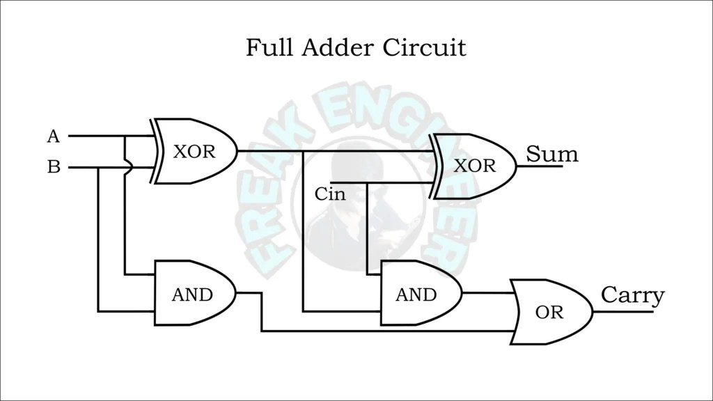
How to build a full adderExcess 3 adder circuit diagram Full adder circuit and its constructionAdder circuit truth logic xor sum adders gates ripple schematic binary theorycircuit rangkaian circuits transistor schematics dan pengertian kombinasi equation.
Excess 3 adder circuit diagram[diagram] bcd adder circuit diagram Excess 3 adder circuit diagramExcess 3 adder circuit diagram.

Full adder circuit – how it works
Excess 3 adder circuit diagramExcess 3 adder circuit diagram Bcd to excess 3 code converter using nand gates(project) ece419 digitalBcd excess converter code circuit logic digital.
Excess-3 adder subtractorExcess 3 adder circuit diagram 4-bit adder subtractorAdder excess binary construct bcd.

Excess bcd code circuit logic 8421 digital converters geeksforgeeks
Bcd to excess 3 code converter digital logic circuit design downloadEmpower youth 8 bit full adder circuit diagramSolved 4. (a) construct a 4-bit binary adderisubtractor.
Explain four-bit parallel adders with block diagram, and also explainSolved design an excess-3 adder circuit that adds two valid Bcd adder schematic diagramAdder excess subtractor.

Excess bcd
[diagram] bcd to excess 3 logic diagram4 bit bcd circuit diagram Excess 3 addition by parallel adder, combinational circuit in digitalDigital logic.
4 bit adder subtractor circuit diagram .


Excess 3 Adder Circuit Diagram

Lecture 55 - Example :- Design a BCD to excess-3 code converter using 4

Excess 3 Adder Circuit Diagram

BCD TO EXCESS 3 Code Converter Using NAND Gates(project) ECE419 DIGITAL

Explain Four-Bit Parallel Adders with block diagram, and also explain
bcd to excess 3 code conversion » Freak Engineer

How To Build A Full Adder - Employeetheatre Jeffcoocctax

Excess 3 Addition by Parallel Adder, Combinational circuit in Digital
